
Tools List
- Electronics Screwdriver Set
- Multimeter
- Soldering Iron
- Solder
- Solder Flux
- Wire
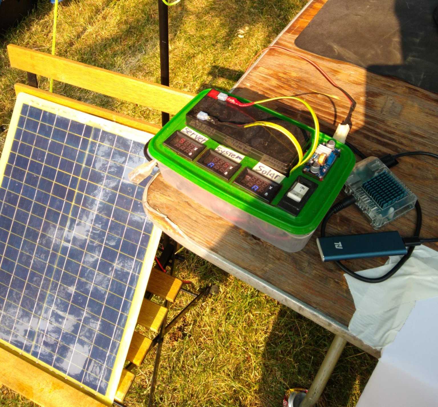
My friend who was a Barista gave us this nice Bonavita electric Kettle when he moved out:

And it worked for years and years, even while we had multiple people living in the house and using the kettle every day.
However, it started getting harder and harder to power it on; I would have to press the power button down for longer and longer to get it to start heating.
Eventually it simply wouldn't turn on anymore at all.
Personally, I've never tried to repair electronics like that. But after my initial experience with DC electronics (making a Lead Acid + solar battery for my Odroid XU4),
and also seeing multiple people pull off soldering projects at Layer Zero, I was inspired to try my hand.
Unfortunately for me, I was immediately confronted with anti-repair practices from Bonavita:
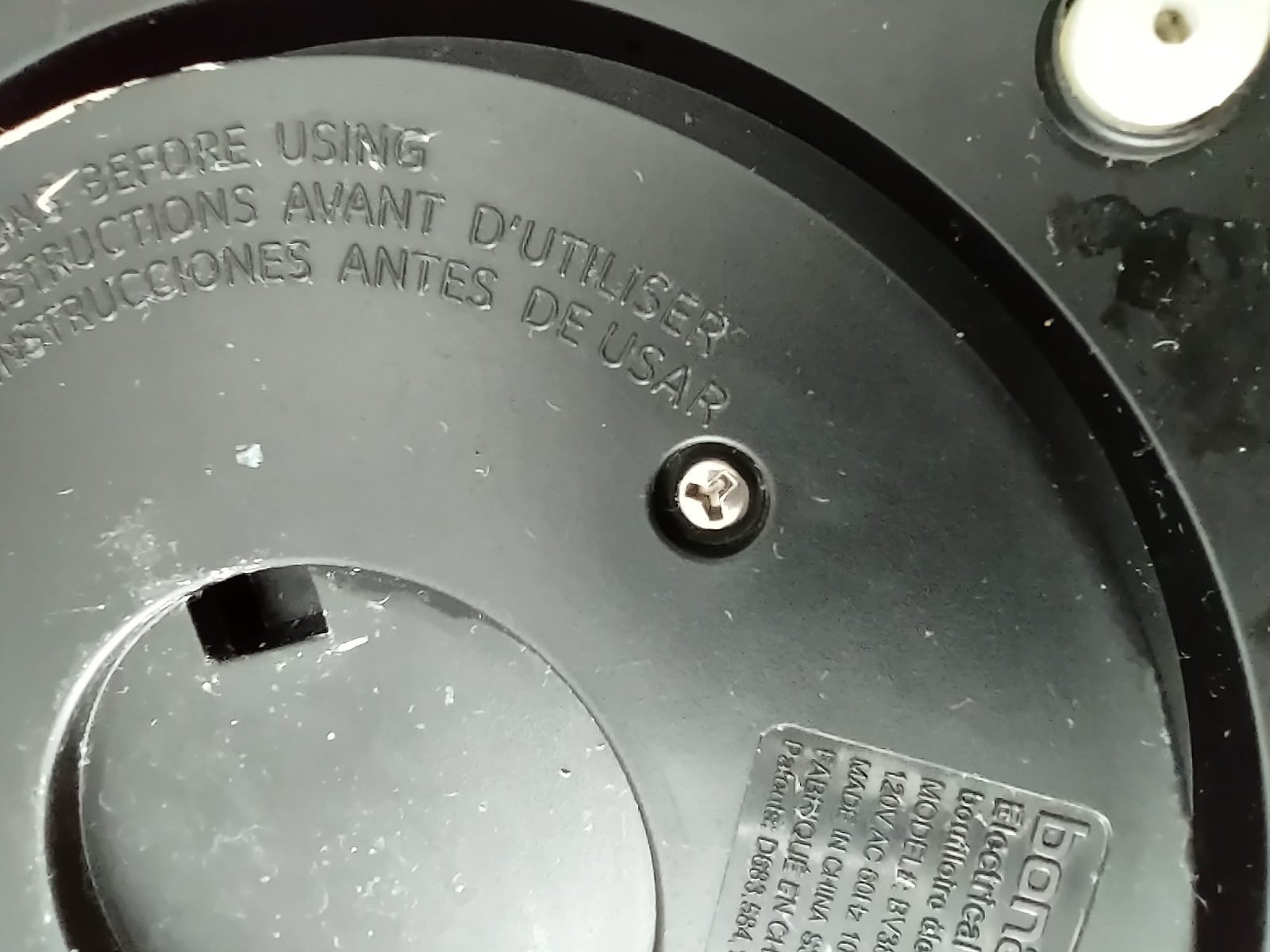
Why the hell do they have tri-lobe screws on the base of this thing? What the actual fuck???
This is especially bizzare once I got the bottom off (I used a flathead small enough to jam into the trilobe, lol).
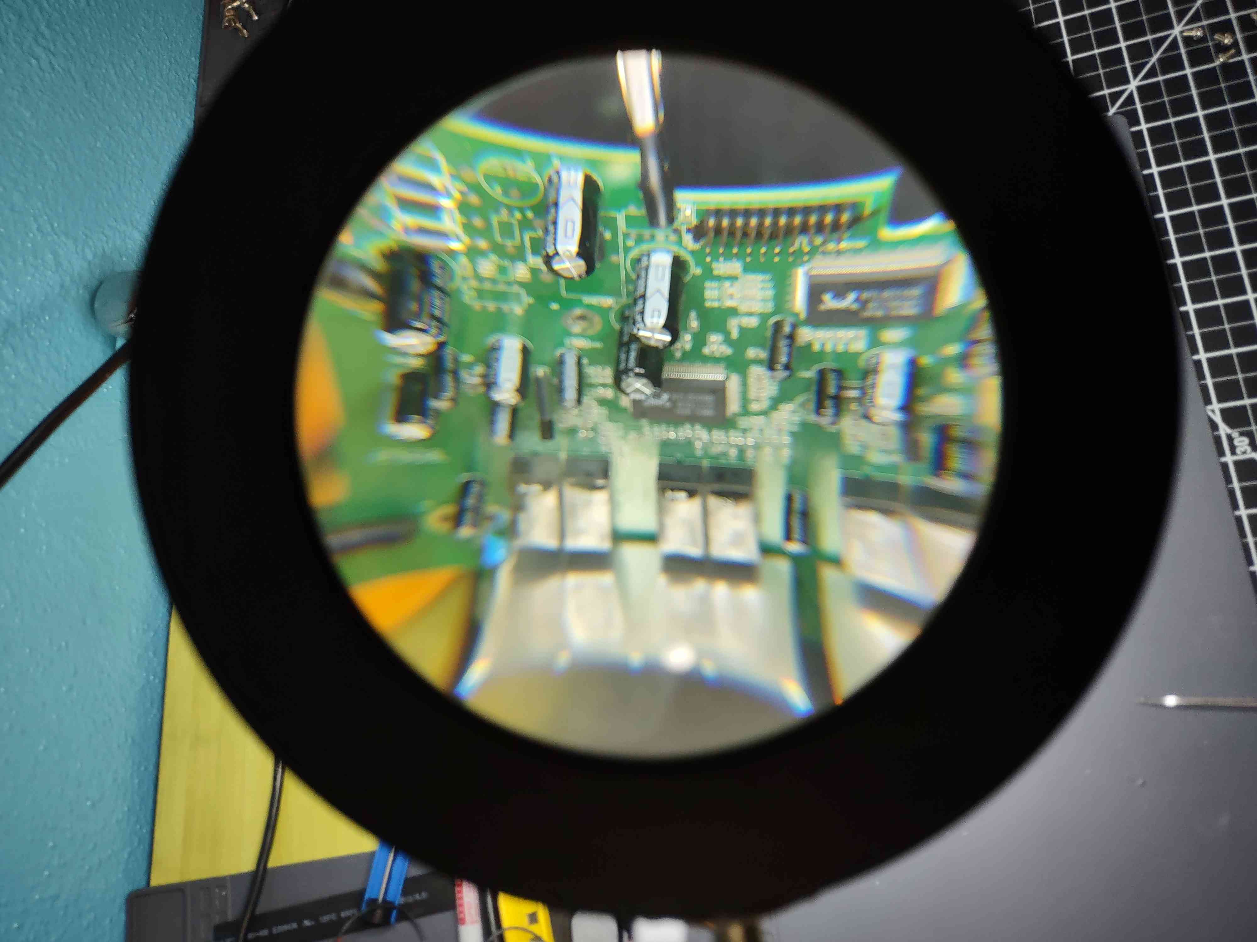
Then I discovered phillips head screws holding the PCBs in place:
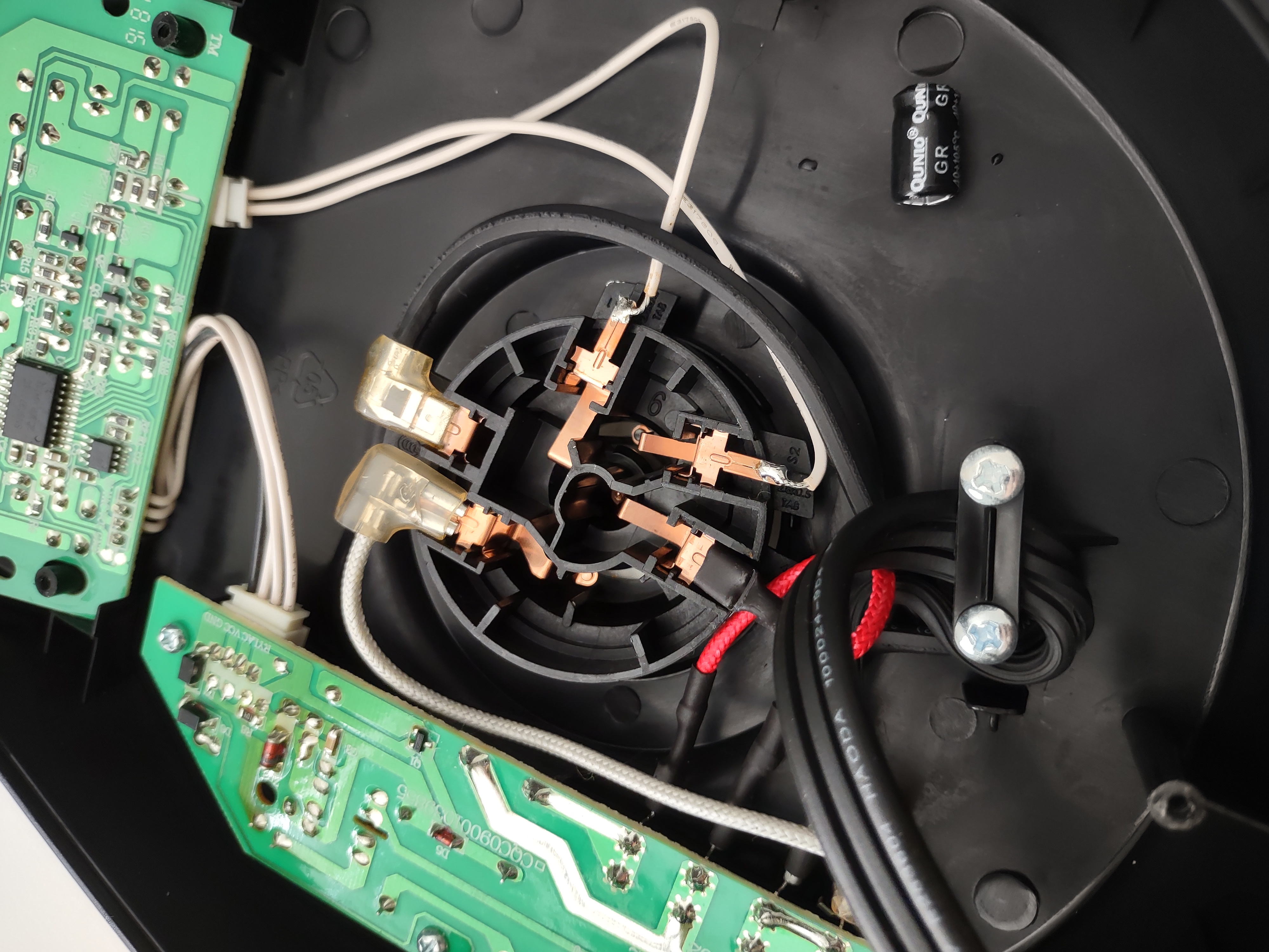
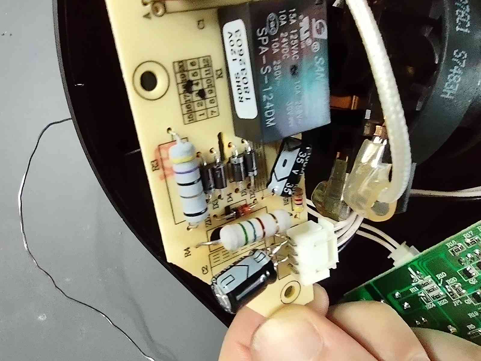
Observant readers may have already spotted something very suspicious on the bottom right: What's that little electrolytic capacitor shroud doing there!?!?!?
Turning over the Power Electronics board, I found where it came from:
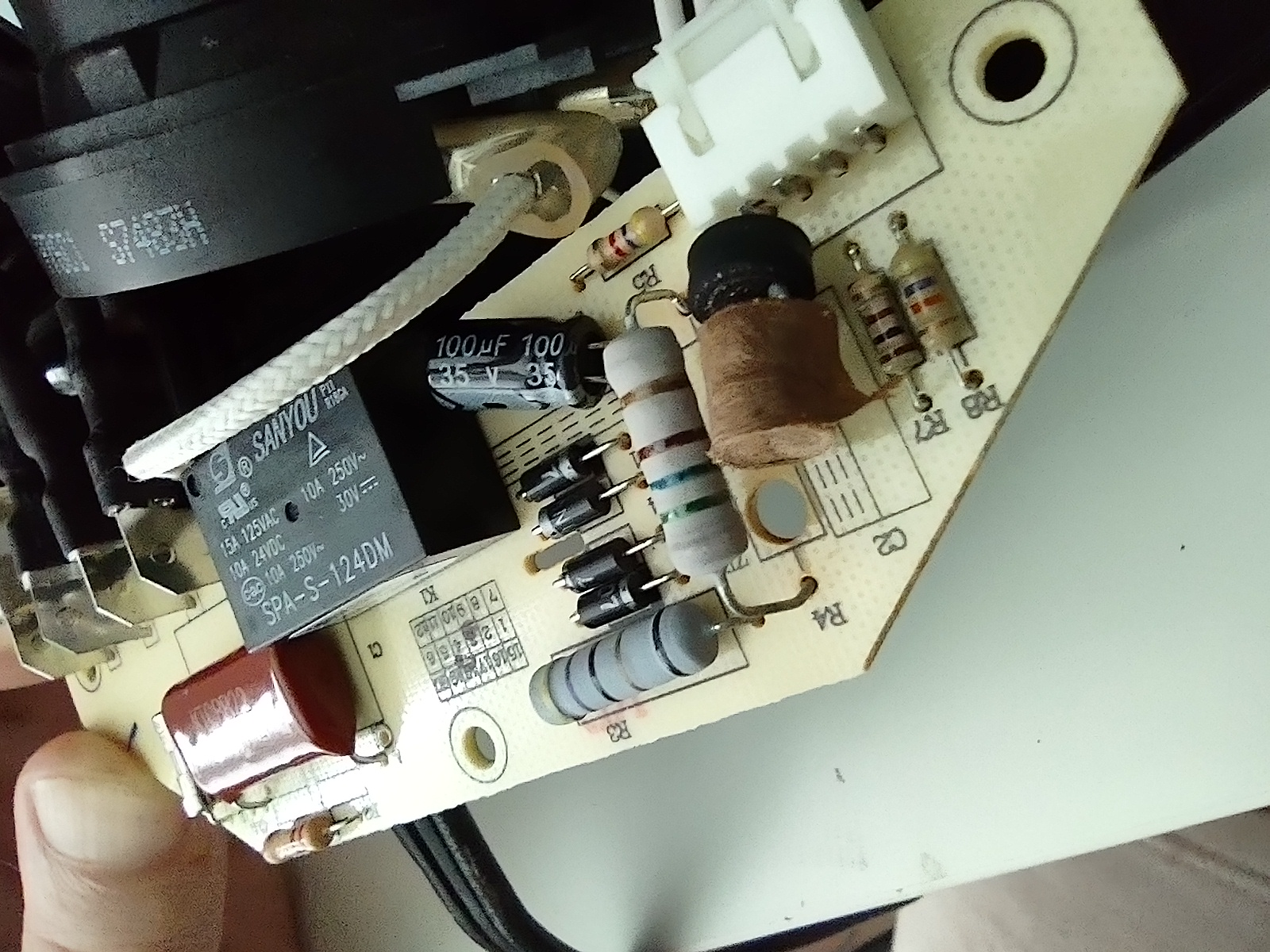
Obviously I found the problem, so got to work replacing this capacitor. (Foreshadowing, lol).
Comments I got on the Cyberia Matrix chat about the project:


Naughty manufacturer putting an electrolytic next to a heating element. You should be fine to replace it. I suggest replacing the other one too.
Later that week, I traveled to Layer Zero where there's a great soldering station and a large pile of tech waste to pick from.
There, I found a capacitor with the exact same matching specs, 16v 470 microfarad, on an old ethernet switch I found in the tech waste bin.
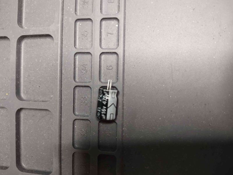
From Ethernet switch
I had de-soldered the replacement capicitor from its home on the ancient ethernet switch's board. Now I had to figure out how to attach it to the Power Electronics board of the kettle.
But first, I had to de-solder the exploded capacitor from the power electronics board.
De-soldering and pulling the broken capacitor off of the boardMusic: Boards of Canada -- poppy seed / everything you do is a balloon
1 minute 0 seconds
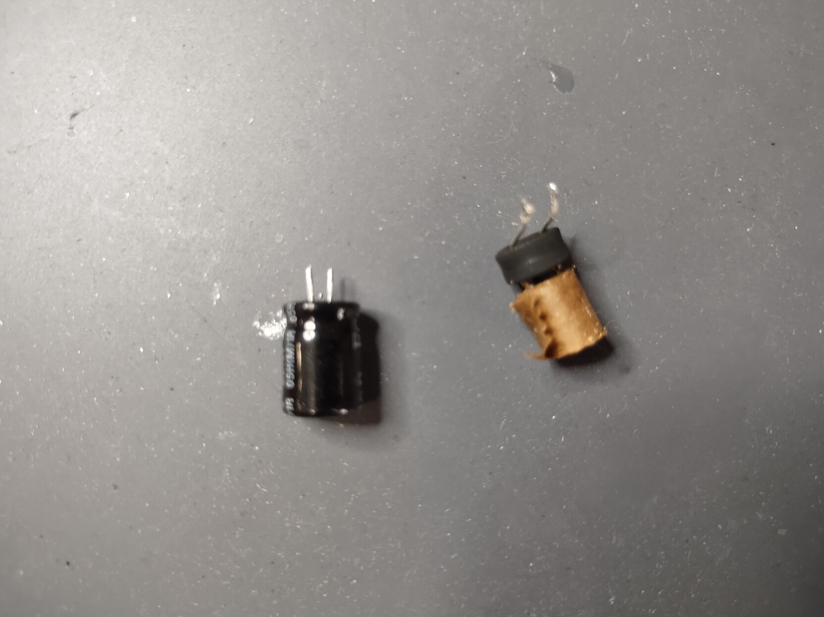
Here are the two capacitors next to each-other, the exploded one and the replacement:
I tried a couple different ways to solder the new capacitor onto the kettle's Power Electronics board.
At first I thought i'd find some thick wire and solder short segments of it onto the holes on the circuitboard, then solder the wires onto the contacts of the capacitor.
However, the only thick wire I could find was braided from a gazzillion smaller strands, and trying to solder it to the PCB was extremely frustrating and taxing.
In the end, I gave up. I couldn't seem to get a clean solder joint with that wire. So next, I thought I'd try a breadboard jumper wire, similar to the one pictured:
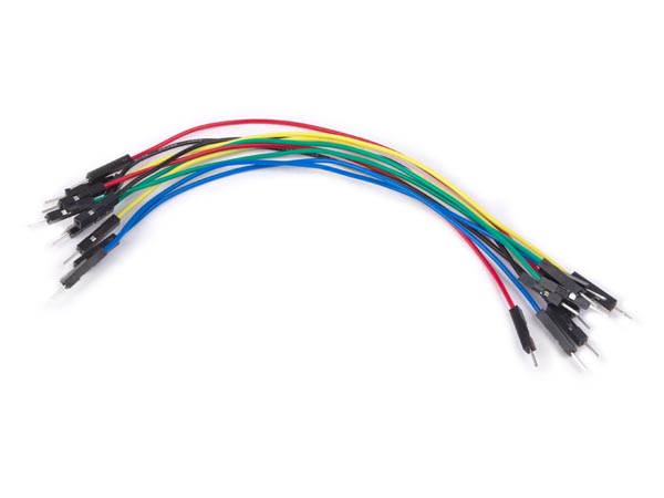
I was able to get a nice secure joint when soldering the ends of one of those onto the board, but wasn't sure how to connect the capacitor.
At first, I tried stripping the middle wire segment. It was hard to strip, the wire was multiple tiny copper strands encased in colorful rubber. It was really hard to remove the rubber without cutting some of the strands.
To make it worse, I wasn't sure if I would have enough space to solder the capacitor onto those copper wires. The plastic end-housings were taking up a lot of real-estate on the tiny board.
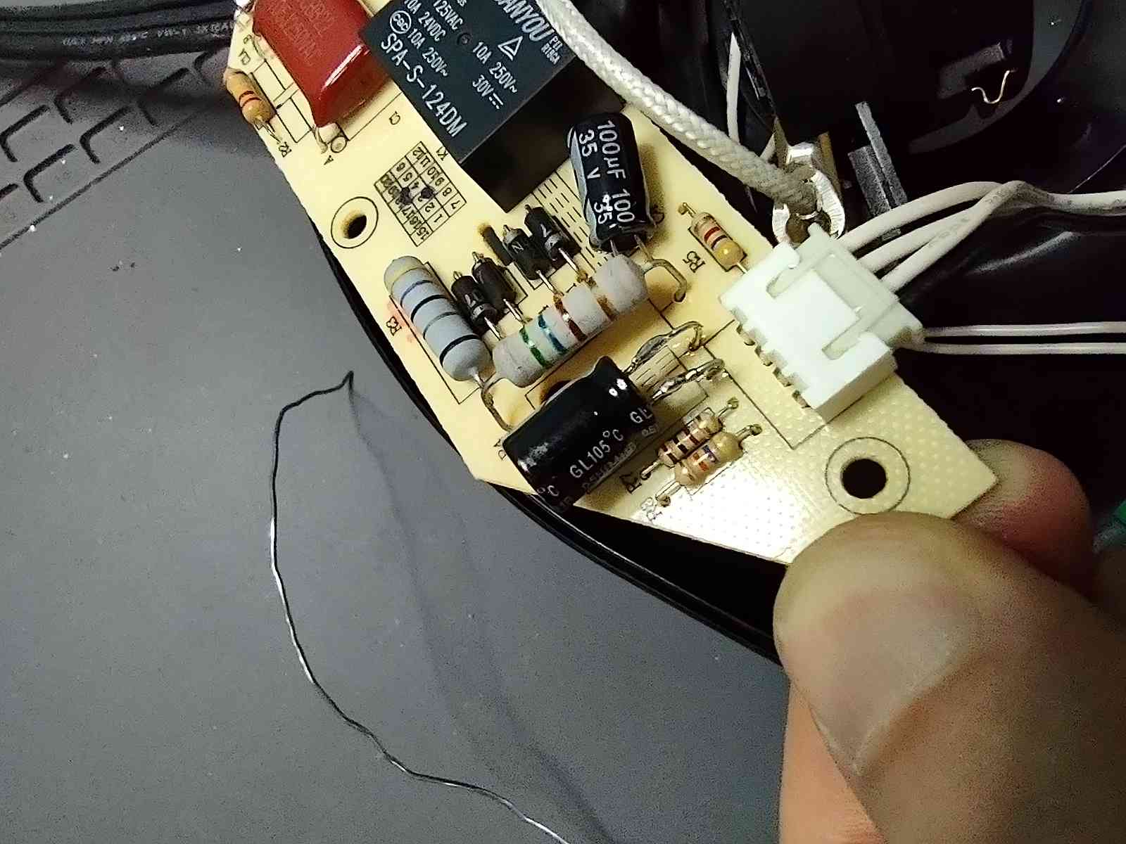
So in the end, I bit the bullet and tried to clip off the plastic end-housings. To my delight, they split off cleanly, leaving just the thick contact wires and little sprigs of copper behind.
After that, I was easily able to bend them into shape, solidify the solder joint to the underlying circuitboard, and finally solder the capacitor onto them.
ℹ️NOTE: I wasn't sure how to tell which way to solder the capacitor -- I'm not sure if they have a "direction" or not like Diodes do. I guessed that they do. But becuase there was another capacitor on the same board, it gave me a clue. The capacitors all seem to have this directional arrow printed on the outside of the housing -- and the circuitboard underneath showed the outline of the capcitor with one side shaded and the other side clear. I assumed via intuition that the shaded side goes with the directional arrow on the outside of the capacitor, because that's what I observed on the one that had not exploded.
Even though this circuitboard has very large features and should be a lot easier to repair compared to a smaller-scale logic board, I still struggled with the solder joints and had to re-do them the first time.
I didn't use any flux at first and quickly regretted it.
Excited, I immediately put the kettle back together, confident it would turn on.
However...
It still seemed very sketchy. When I pressed the power button, nothing happened. I had to press it multiple times and hold it down for multiple seconds before the kettle finally sprung to life and started heating.
😰
                                              ░░
                                                                          ░░
              ░░                              ░░                          ░░
              ░░        ░░                    ░░                        ░░░░
              ░░    ░░  ░░                    ░░      ░░                ░░░░            ░░
      ░░      ░░    ░░  ░░      ░░            ▒▒      ░░    ░░            ░░            ░░
░░  ░░░░      ░░    ░░  ░░  ░░  ░░            ▓▓      ░░    ░░░░          ░░            ░░
░░░░░░░░      ░░    ░░  ░░░░▒▒░░░░        ░░  ▓▓░░    ░░    ░░      ░░  ░░    ░░░░      ░░  ░░
▒▒░░  ░░      ░░  ░░░░  ▒▒░░▓▓░░░░░░      ▒▒  ▓▓▒▒    ░░  ░░░░  ░░  ░░  ░░  ░░░░░░    ░░░░  ░░
▒▒░░▒▒▒▒░░    ▒▒░░░░░░  ▒▒░░▓▓░░░░░░      ▒▒░░██▒▒░░░░░░  ░░▒▒░░░░░░▒▒  ▒▒░░░░░░░░    ░░░░  ▒▒
▒▒░░▒▒▒▒░░  ░░▒▒░░░░░░░░▒▒▒▒▒▒▒▒▒▒░░░░  ░░▒▒░░▓▓▒▒░░░░▒▒  ▒▒▒▒▓▓░░▓▓▒▒▒▒  ░░▒▒▒▒▒▒░░▒▒▒▒░░░░▒▒
▒▒▒▒▓▓▒▒░░░░░░▒▒▒▒░░▒▒░░▒▒▒▒▒▒▒▒▒▒░░▒▒░░▒▒▓▓░░▓▓▒▒▒▒░░▒▒░░▒▒▒▒██  ▓▓▒▒░░▒▒  ▒▒▓▓▒▒░░▒▒▒▒  ▒▒██
▒▒▒▒▓▓▒▒▒▒░░▒▒▒▒▒▒▒▒▓▓░░▒▒▒▒▒▒▓▓▒▒░░▓▓░░▒▒▒▒░░▓▓▒▒▒▒▒▒▓▓▒▒▓▓░░██░░▓▓▒▒▒▒▓▓░░▒▒▓▓▒▒▒▒▒▒▓▓▒▒▒▒██
▒▒▓▓▓▓▓▓▒▒▒▒▒▒▒▒░░▓▓▓▓▒▒▒▒▒▒▓▓██░░▒▒▒▒▒▒▓▓░░▒▒▒▒▒▒▒▒▓▓██░░██▒▒▓▓░░░░▓▓▒▒▓▓░░▒▒▓▓▓▓▒▒▒▒▓▓▒▒▒▒▓▓
▒▒▓▓▒▒▒▒▓▓██░░▓▓░░▒▒▓▓▒▒▒▒▓▓▓▓██░░▒▒▒▒▓▓▒▒░░▒▒░░▒▒░░▓▓▓▓░░▒▒░░▒▒▒▒░░▓▓▒▒▓▓  ░░▓▓▓▓▓▓▒▒▒▒▒▒░░░░
▒▒▓▓░░▒▒▒▒▒▒░░░░░░▒▒▒▒▒▒▒▒▒▒▒▒▓▓░░░░░░▓▓░░░░▒▒░░▒▒░░▓▓▒▒░░░░░░▒▒▒▒░░▓▓▒▒▓▓  ▒▒░░▒▒▒▒▒▒▒▒▓▓▒▒
░░▒▒  ▒▒░░▒▒  ░░▒▒░░  ░░▒▒▓▓▒▒▓▓░░  ░░▓▓▒▒  ░░░░▓▓  ▒▒░░░░░░  ██▒▒  ▒▒░░▓▓░░▒▒░░▒▒░░▒▒▒▒▓▓▒▒
░░░░  ▒▒▒▒░░░░  ▒▒  ▒▒  ▒▒░░░░▓▓  ░░░░▒▒░░  ░░░░▒▒  ▒▒░░    ░░░░▒▒  ▒▒░░▓▓▒▒▒▒  ░░  ▒▒░░▒▒▒▒
      ░░░░░░░░░░    ░░░░▒▒▒▒  ░░      ▒▒░░  ░░░░░░  ▒▒░░      ░░▒▒░░░░░░░░▒▒░░      ▒▒░░░░▒▒
░░    ░░  ░░        ░░  ▒▒░░  ░░            ░░░░░░  ▒▒░░        ░░  ░░░░░░░░░░      ░░░░░░░░
      ░░░░  ░░  ░░      ░░    ░░        ░░    ░░    ▒▒░░        ░░  ░░  ░░░░        ▒▒░░░░░░
      ░░░░                              ░░          ▒▒░░                                  ░░
      ░░░░                              ░░          ░░                      ░░
      ░░░░                              ░░      ░░
After a few days off from the project, I came back with a fresh look.
Before I opened it, my intuition had been that the power button was dying.
Does anyone have tri lobe screw driver(s)?
We have this nice electric kettle thingy
It stopped working, my suspicion is that the power button wore out
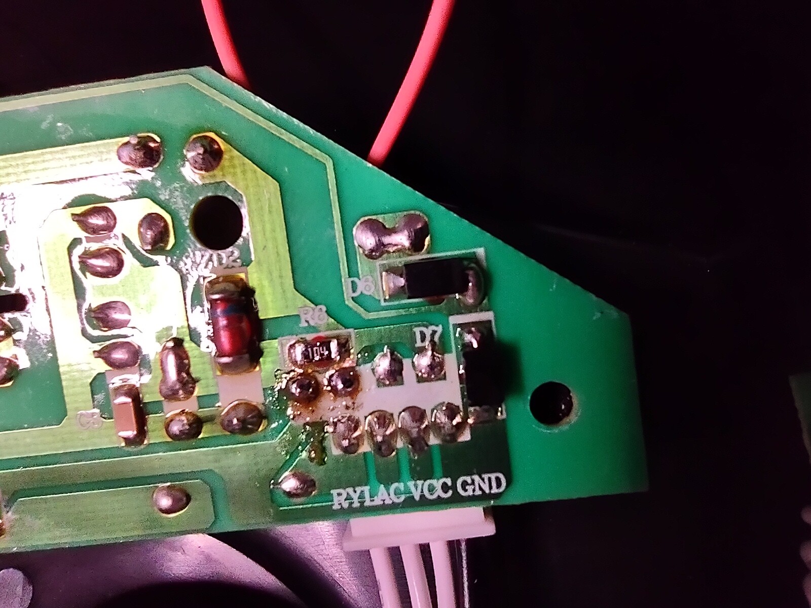
Upon re-inspection, I was able to tell that the voltage going to the control board seemed to be fine -- I saw a steady 5v DC on the header pins labeled VCC / GND
When I'd talked to my partner about it, they'd mentioned that they'd observed a difference betwen simply pressing the power button and dragging one's finger across it deliberately perpendicular to the switch's direction of travel -- and that sometimes dragging caused it to work better.
I had never noticed this, and it gave me a suspicion that perhaps my original idea, the power button, was right all along.
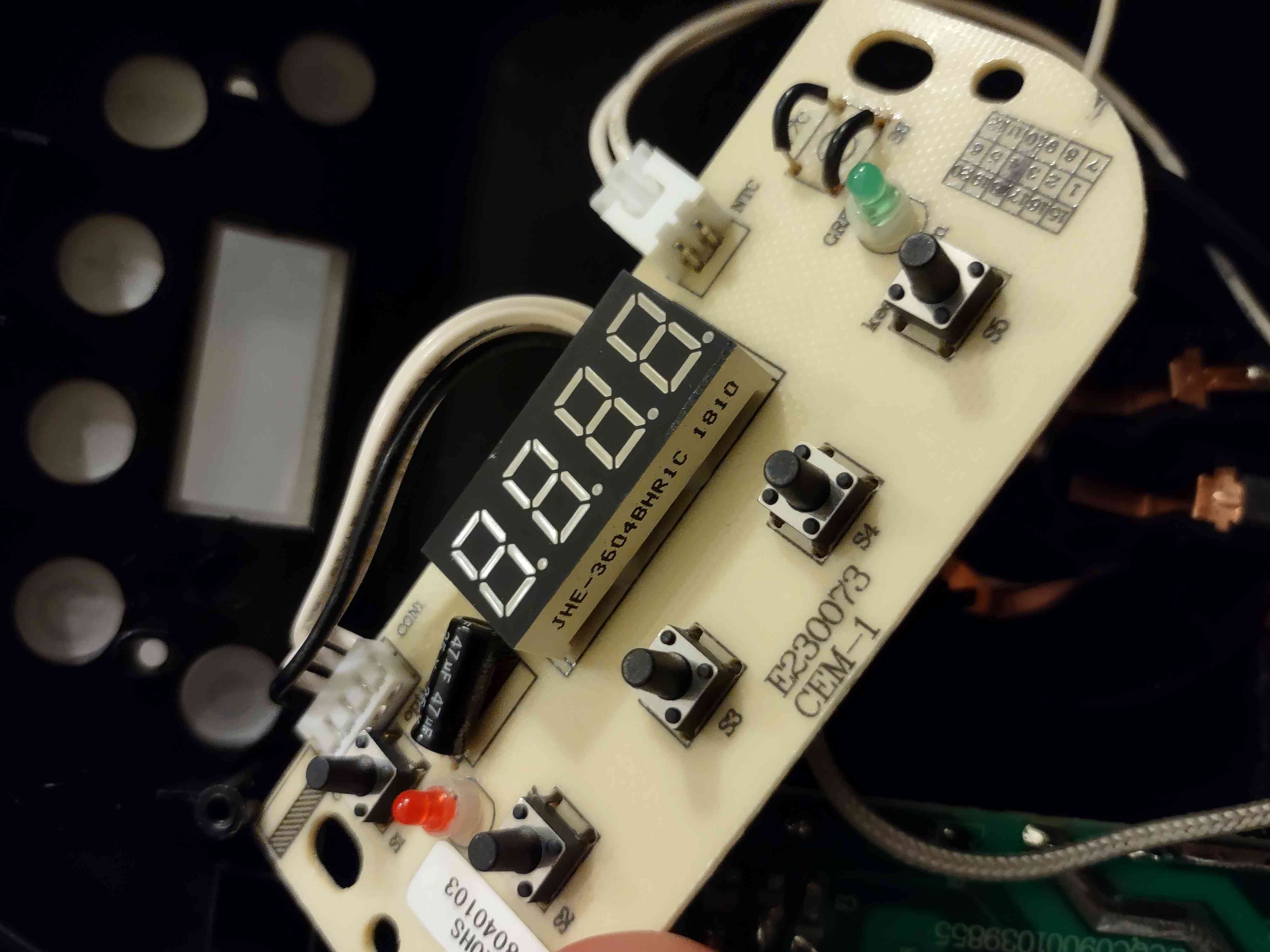
So I opened the stinker up again and started looking at the digital control board and all the switches on it.
ℹ️NOTE: I had a humbling experience with this... When I was a kid, my father gave me a
TENMA 72-7720multimeter as a birthday gift.This thing definitely works,
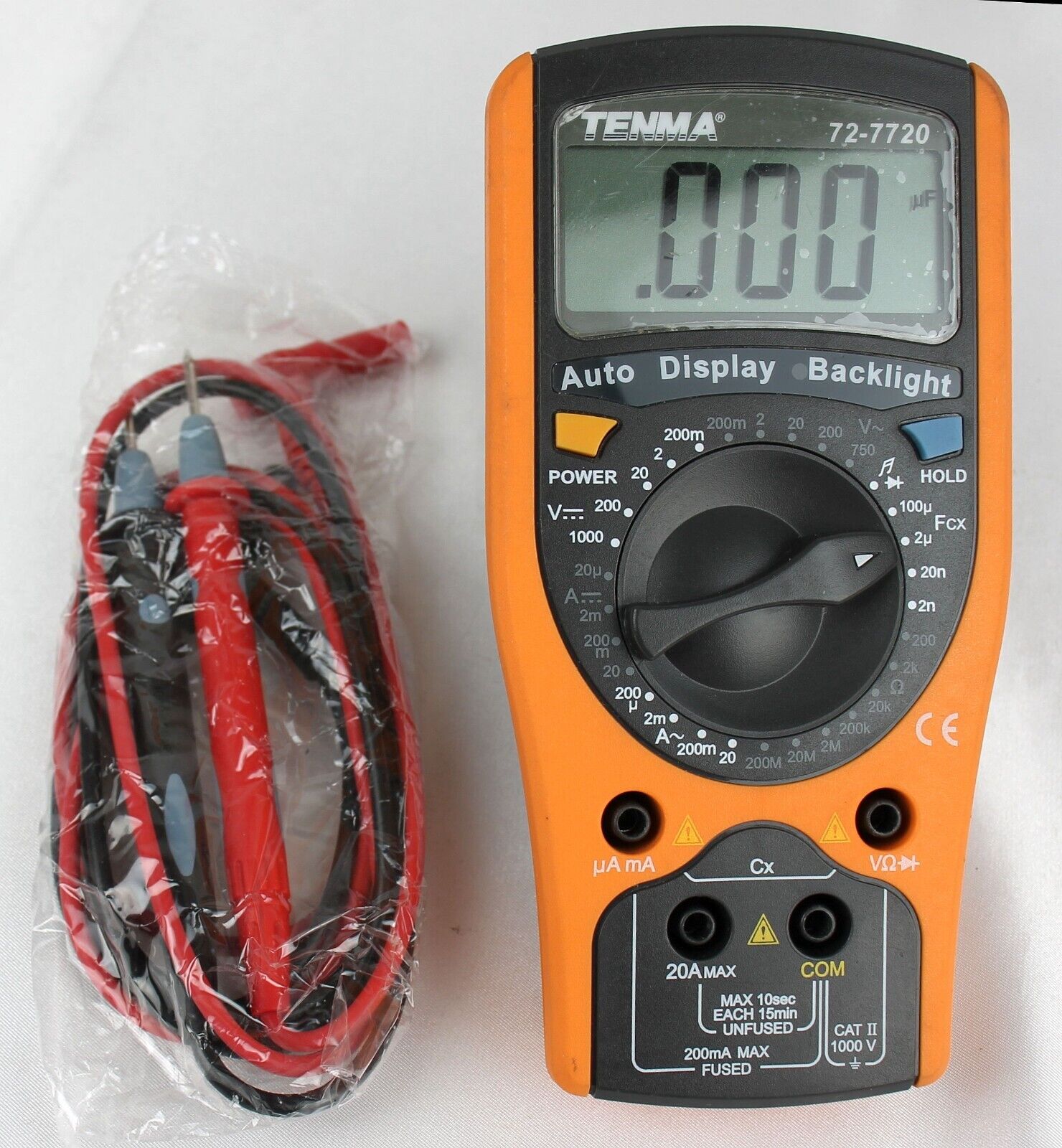
however, it's slow to update its display, and requires manual adjustment to get to the right setting for probing whatever circuit you might be faced with.
At Layer Zero, someone donated a modern
Fluke 117multimeter. It makes a world of difference. It automatically detects the range of the measurement instead of requiring the user to select it, and it updates its display instantaneously. It also features a log-scale display of the measurement in the form of a segmented bar display-- this ended up being a lifesaver for this project.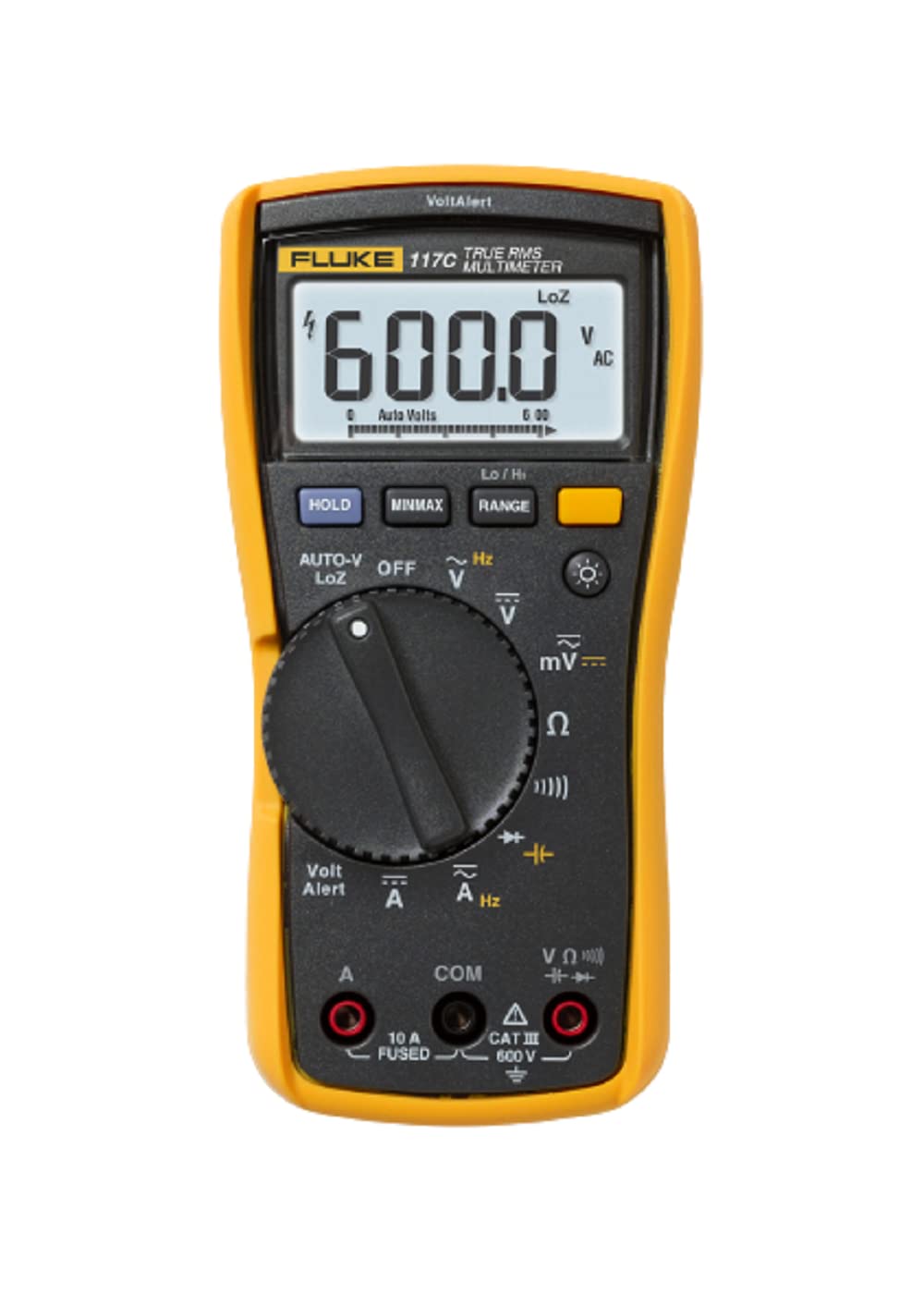
I recognized the Fluke brand name as a quality brand from listening to the Marco Reps youtube channel, and this thing definitely did not dissapoint.
Using the Fluke at Layer Zero, connecting the probes across the power switch pins, I saw something very interesting which I had missed with the Tenma.
ℹ️ INFO: In part, this was due to my ignorance combined with the un-repair-ability of the Bonavita kettle. The kettle's digital control circuitboard's bottom side had been coated with some sort of insulating material -- I had to scrape and scrape and scrape at the solder joints before I could get any reading at all. To be fair, there's probably a good reason for this coating.. But it's annoying when I'm trying to fix the thing.
The view from the Tenma was just confusing -- I wasn't physically able to hold the probes steady in place for long enough to see a change within whatever narrow sensing range I had selected. Even after I started agressively scraping the coating off.
But once I had it under the Fluke at Layer Zero, I started seeing things. The real-time display (less than 10ms update latency) really illuminated the problem. Basically, the power button switch was toasted.
Instead of showing "infinity" ohms when it was open, it showed about 4 mega-ohms. When I scraped the coating off of other switches on the control board and tested them, they showed infinity ohms when open.
When the power switch was "closed" (power button pressed), the measurement would vary wildly between mega ohms, kilo ohms, etc, as I wiggled my finger around on the power button. The log scale display bar on the bottom of the Fluke's LCD made this obvious. This explains what my partner had experienced w/ directionality of the way they pressed the button influencing success rate!
So, I decided to replace the power button. Looking around at all the other buttons on the device, I decided I would sacrifice the Centigrade / Farenheit toggle button, and use it to replace the power button.
This went fairly easily, I had to melt and detach one 2-pin side of the 4-pin button at a time, but besides that, I didn't have any issues.
However.....
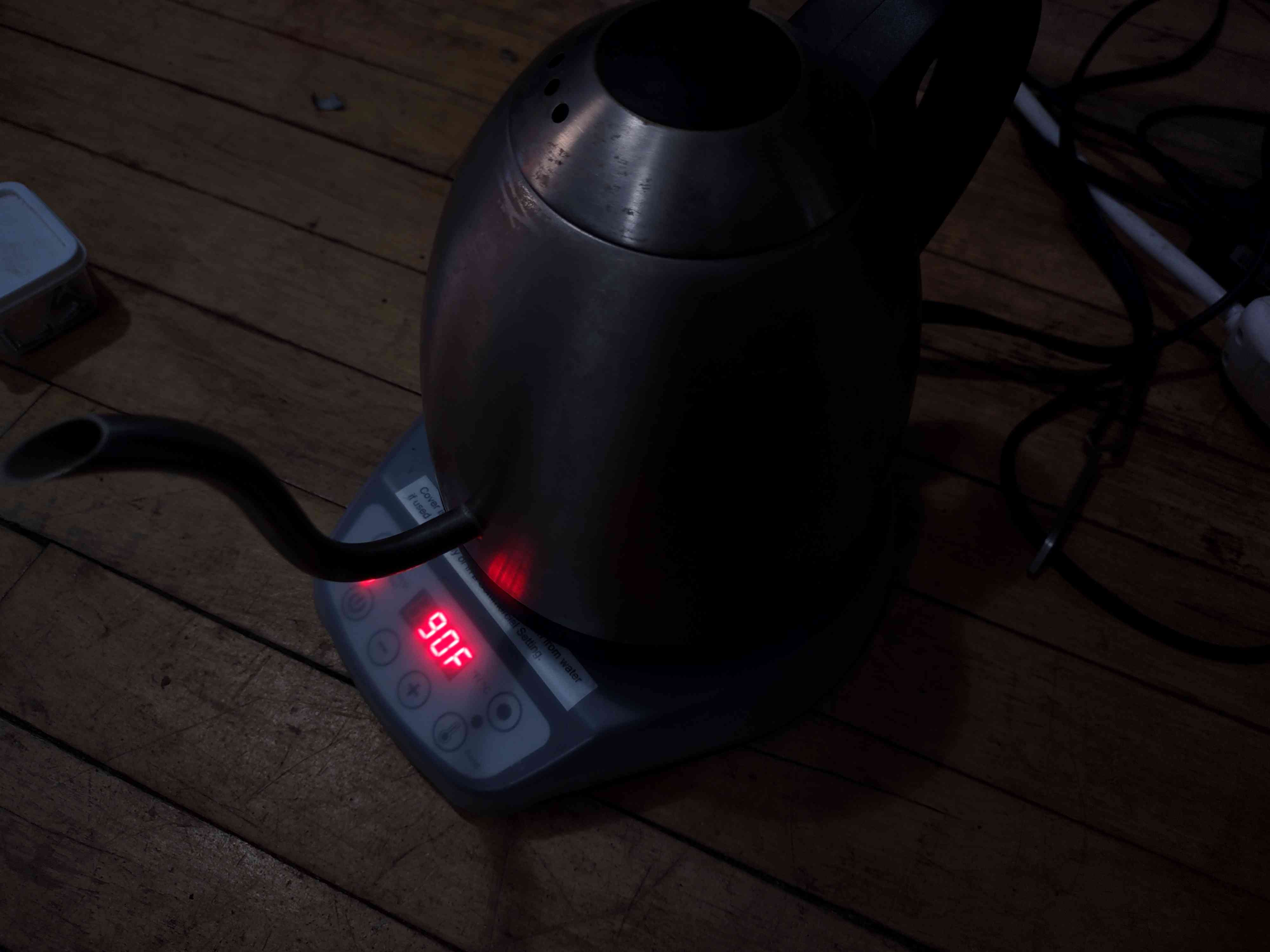
I put the thing back together again, and excitedly pushed the power button. To my delight, it instantly sprang to life on the first try, unlike before. I thought it was FIXED!!!!
....
I was wrong. After it turned on, instead of starting to heat, it clicked off and displayed 0F on the LCD.
....
Further investigation revealed that the switch I had removed was in fact an important part of the circuit for the temperature sensing feature -- It was the only switch on the board for whoom the horizontal sides of the switch bridged a PCB trace.
Pin Layout of Every Switch on the Board Except the Celcius / Fahrenhiet switch:
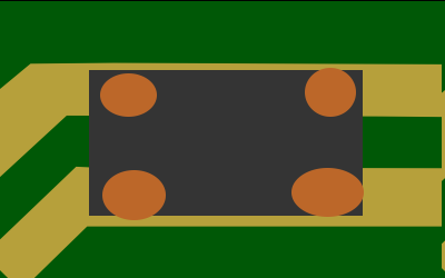
Pin Layout of the Celcius / Fahrenhiet switch:

It turns out that because of the type of switch the manufacturer had used, according to my housemate who's a technician / engineer,
Single pole double throw switch
By removing the Celcius / Fahrenhiet switch I had broken the device. The switch was conducting between those two wires by default until it was pressed, but I had broken that connection by removing it.
So, finally, I got a couple small segements of wire and soldered them long-ways across the place where the switch had originally been:
Comments